MikroTik Router Setup with Multiple VLANs
Article · · 12 minutes to read · Jacob Barnes
Introduction
MikroTik routers are awesome! I recently purchased a hAP ac2 and have been very happy with it. Unfortunately, the UI is not very intuitive (especially compared to my old Ubiquiti router) but there are so many options that you can use to configure advanced network setups! I could not find many good tutorials on the internet, so I figured that I would help everyone out by writing my own.
What we are building
This tutorial assumes that your router is still on the default configuration (or “defconf”) and your router has been upgraded to RouterOS 7.8.
I will not be covering how to configure internet access in this tutorial and I will assume it has already been configured.
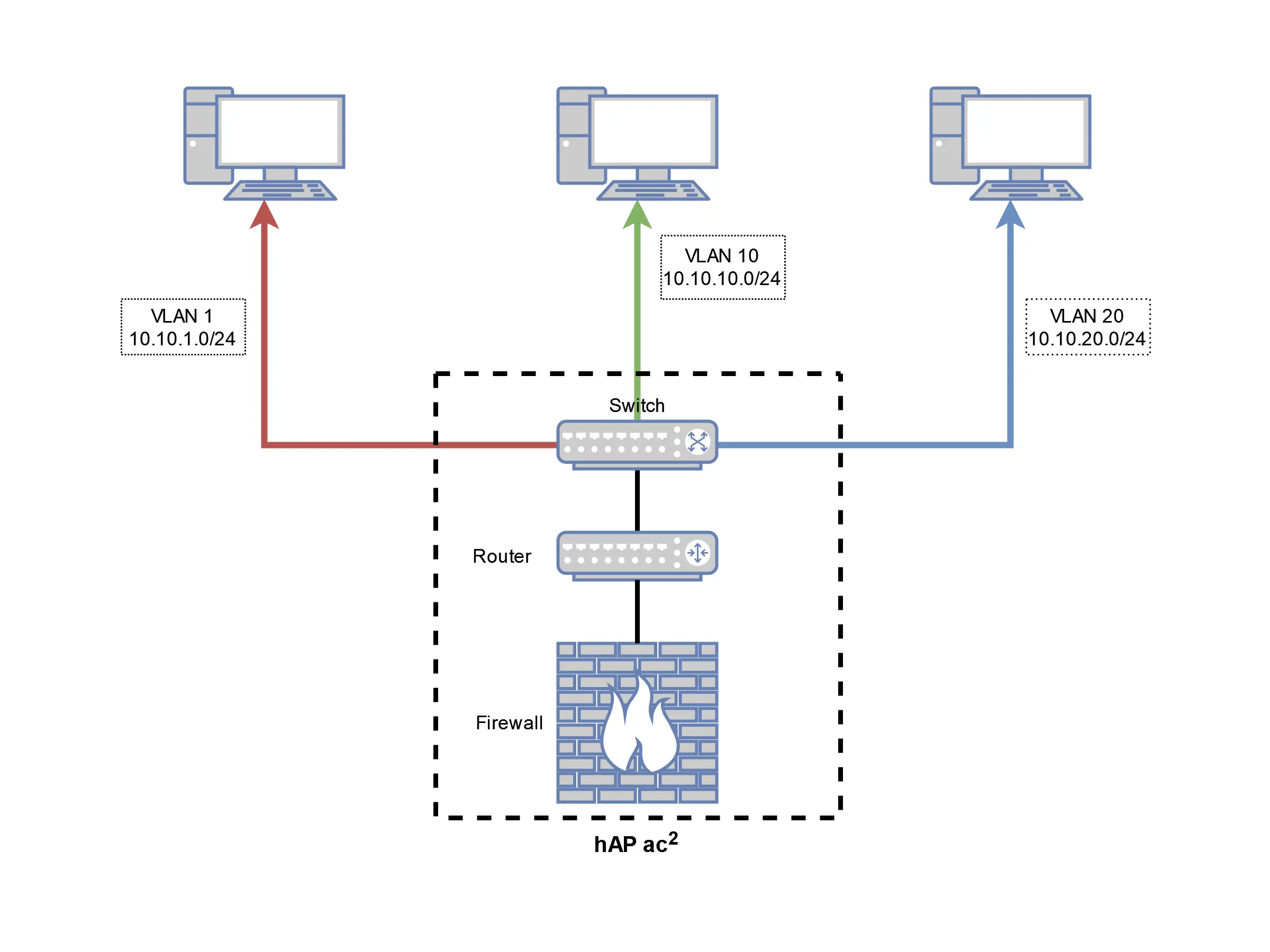
In this tutorial, we will be building a network with 3 different VLANs, which are represented by the colors in the diagram:
- Red: Default VLAN (ID: 1, Subnet: 10.10.1.0/24)
- Green: User VLAN (ID: 10, Subnet: 10.10.10.0/24)
- Blue: Server VLAN (ID: 20, Subnet: 10.10.20.0/24)
As you can see in the diagram, we will be using the switch, router, and firewall that is built in to the hAP ac2 for our example network config.
This tutorial will be covered in 3 different parts:
- Creating and configuring the VLANs
- Setting up network services for each VLAN (DHCP, etc.)
- Securing the VLANs
Creating and configuring VLANs
By default, our bridge network is already configured to the correct IP address range and our router’s IP is set to 10.10.1.1. This will serve as our default VLAN.
Let’s begin by creating the new VLANs and assigning their addresses.
-
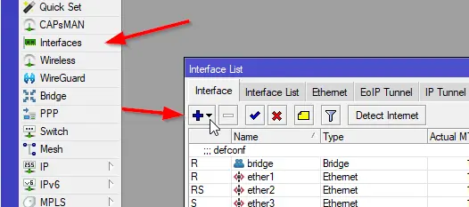
Open the “Interfaces” menu, click the “+” button, and select “VLAN”.
-
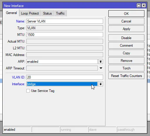
A new window will appear. For the follwing fields, enter:
Leave the rest of the fields set as their defaults and click “OK”.- Name:
User VLAN(can be whatever you want to name it) - VLAN ID:
10 - Interface:
bridge

- Name:
-
Repeat Step 2 and enter the following information to create the Server VLAN:
Again, leave the rest of the fields as the default values and click “OK”.- Name:
Server VLAN(can be whatever you want to name it) - VLAN ID:
20 - Interface:
bridge
- Name:
-
In the “Interfaces” window, we now see our new VLANs

-
We need to add our new interfaces to the “LAN” list on the router. This is used by the firewall to allow traffic for services like DNS.
Click the “Interface List” tab in the “Interfaces” window. Click the “+” button and add the User VLAN to the “LAN” list by entering these options:WarningThis will also allow traffic from all networks to connect to WinBox. If you want to restrict access to WinBox to only the management network (recommended), there will be an example in the “Securing the VLANs” section at the end.- List:
LAN - Interface:
User VLAN
 Do the same for the Server VLAN:
- List:
LAN - Interface:
Server VLAN
- List:
-
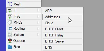
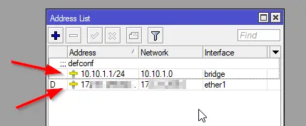
Open the “Addresses” menu.
 You can see the 2 addresses that have already been added: one for the bridge and one for our external interface (the interface that is connected to your ISP)
-
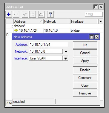
We now want to add the address spaces for our new network so our router is aware and can route the packets to their proper network. Click the “+” button and enter the following values in the dialog:
Click “OK” to save your settings.- Address:
10.10.10.1/24 - Network:
10.10.10.0 - Interface:
User VLAN
 Click the “+” button again and add the following values for the Server VLAN:
Click “OK” to save your settings.
Click the “+” button again and add the following values for the Server VLAN:
Click “OK” to save your settings.- Address:
10.10.20.1/24 - Network:
10.10.20.0 - Interface:
Server VLAN
- Address:
-
As you can see, all our networks have been added.
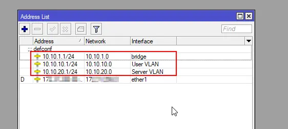
At this point, the router should route our traffic across the VLANs.
Setting up network services for each VLAN
If you were to connect your computer to a port on the Mikrotik, it would currently route all your traffic through the default VLAN.
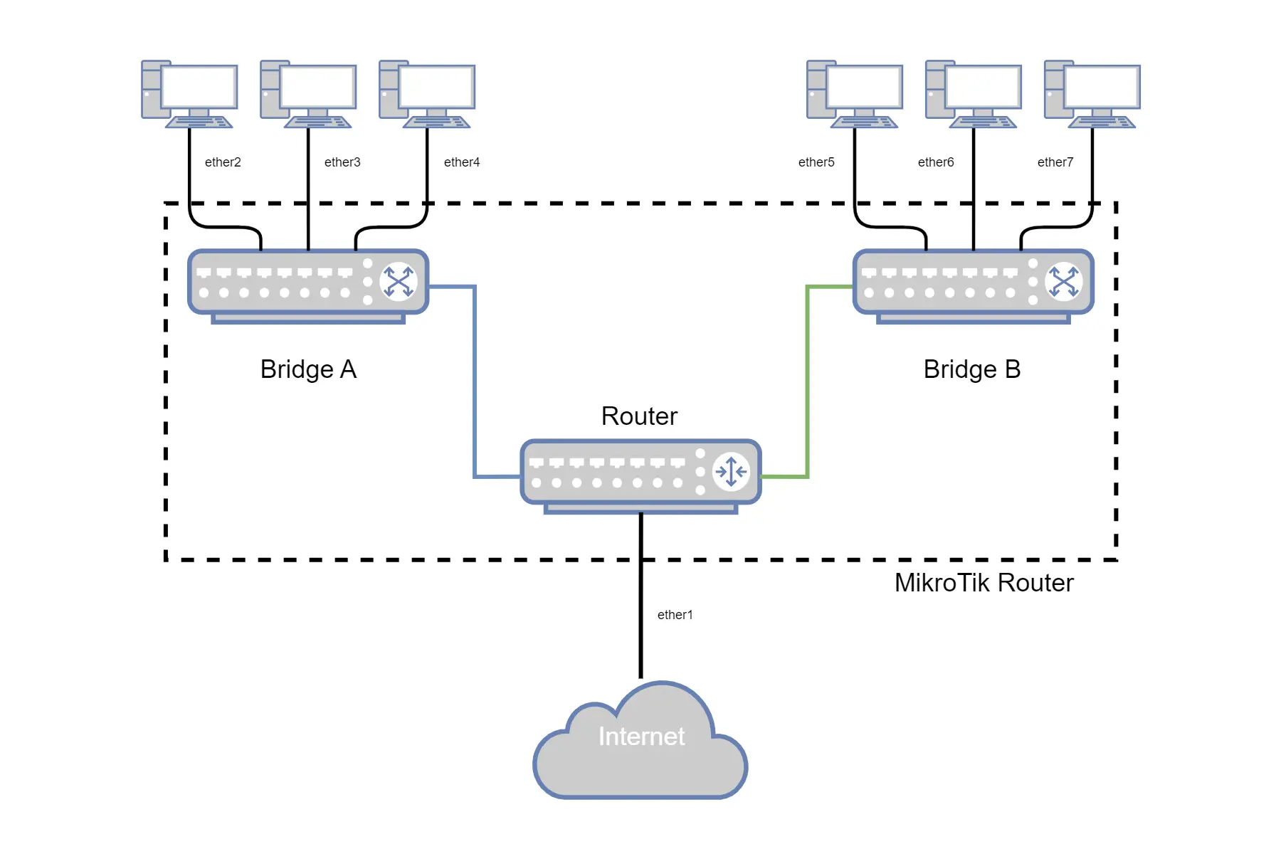
We can configure the ports to route traffic to a VLAN we have configured. This is set up through a “Bridge”.
A Bridge is effectively a virtual switch where one port is always connected to the router. We can configure the ports connected to the bridge so they send traffic to a specific VLAN, and the traffic will be automatically routed. This works even if the ports are all connected to the same bridge.
If you connect ports to separate bridges, the router will treat this as a completely separate network and traffic will not be routed between them by default.
Example:
- ether1 -> Internet
- ether2-4 -> Bridge A
- ether5-7 -> Bridge B
Traffic from Bridge A will not be routed to Bridge B by default because there are no routes set up for that. However, the default configuration of the router allows traffic to be routed correctly out to the internet, no matter which bridge a device is connected to.
-
Open the “Bridge” menu from the sidebar and select the “Ports” tab.
 Here we can see all the ports that are currently connected to our bridge. You will not see “ether1” because it is our external interface.
Instead, it is connected directly to the router, and traffic is routed to the internet
Here we can see all the ports that are currently connected to our bridge. You will not see “ether1” because it is our external interface.
Instead, it is connected directly to the router, and traffic is routed to the internet

-
Let’s leave “ether2” connected to our default VLAN and connect “ether3” and “ether4” to VLANs 10 and 20, respectively.
Double-click “ether3” from the list and select the “VLAN” tab. Update the “PVID” to10and click “OK” to save. Do the same for “ether4” but set “PVID” to
 20. Click “OK” to save. -
Now we need to add our VLAN Ids to our bridge. In the “Bridge” menu, click the “VLANs” tab and click the “+” button. Enter the following options for the User VLAN:
- Bridge:
bridge - VLAN IDs:
10 - Tagged:
bridge
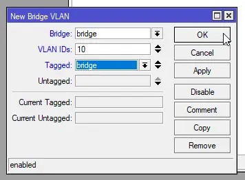 Click the “+” button again and enter the following options for the Server VLAN:
- Bridge:
bridge - VLAN IDs:
20 - Tagged:
bridge
- Bridge:
If we connect a device to port 3 or port 4, it should be able to communicate now. The only problem is that we will have to manually assign an IP address for each device. Manually assigning IP addresses for every device will quickly become frustrating and cumbersome, so we will set up DHCP, which will assign IP addresses automatically.
-
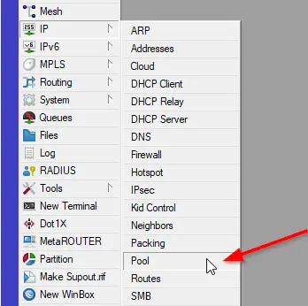
To set up DHCP, we first need to set up the groups of addresses that will be assigned to devices. These groups are called “Address Pools”. To set up the address pools for our network, open the “Pool” window by opening the “IP” menu in the sidebar and selecting “Pool”.
-
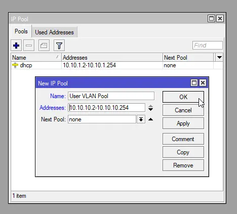
We will create 2 Pools, one for the User VLAN and one for the Server VLAN. Click the “+” button and enter the following information for the User VLAN:
- Name:
User VLAN Pool - Addresses:
10.10.10.2-10.10.10.254 - Next Pool:
none(default value)
 Do the same for the Server VLAN and enter the following:
We can now see our new address pools in the list.
Do the same for the Server VLAN and enter the following:
We can now see our new address pools in the list.- Name:
Server VLAN Pool - Addresses:
10.10.20.2-10.10.20.254 - Next Pool:
none(default value)
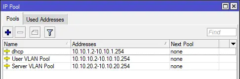
- Name:
-
Now we can configure the DHCP servers for our network. Open the “DHCP Server” menu by opening the “IP” menu and then selecting “DHCP Server”.
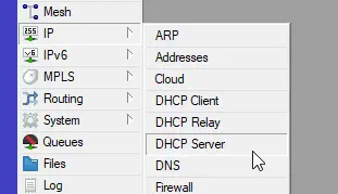
-
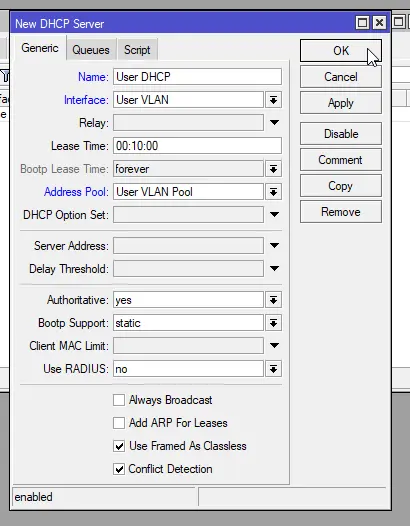
On the “DHCP Server” menu, click the “+” button to add a new server. In the dialog, enter the following settings for the User VLAN and leave the rest as default:
- Name:
User DHCP - Interface:
User VLAN - Address Pool:
User VLAN Pool
 Do the same for the Server VLAN:
The new servers will now be listed in the “DHCP Server” list.
Do the same for the Server VLAN:
The new servers will now be listed in the “DHCP Server” list.- Name:
Server DHCP - Interface:
Server VLAN - Address Pool:
Server VLAN Pool
- Name:
-
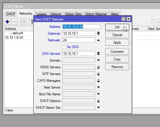
Now we need to tell our DHCP server what network it needs to assign IP addresses to. Click the “Networks” tab in the “DHCP Server” window and click the “+” button. A new window will appear.
Input the following information for the User VLAN:NoteIn addition to telling the router what network to assign IP addresses to, we also use these settings to configure DNS Servers and other options (like PXE Boot, NTP servers, etc).- Address:
10.10.10.0/24 - Gateway:
10.10.10.1 - Netmask:
24 - DNS Servers:
10.10.10.1
 Click the “+” button again and enter the following settings for the Server VLAN:
- Address:
10.10.20.0/24 - Gateway:
10.10.20.1 - Netmask:
24 - DNS Servers:
10.10.20.1
- Address:
If you connect a device to ports 2, 3, or 4 on your router, it should get an IP address for the correct network.
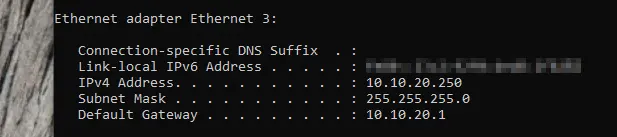
On Windows: Run the On MacOS: Run the On Linux: Run the How to check your IP configuration
ipconfig command.C:\Users\youruser>ipconfig
Windows IP Configuration
Ethernet adapter Ethernet 3:
Connection-specific DNS Suffix . :
Link-local IPv6 Address . . . . . : <redacted>
IPv4 Address. . . . . . . . . . . : 10.10.10.254
Subnet Mask . . . . . . . . . . . : 255.255.255.0
Default Gateway . . . . . . . . . : 10.10.10.1
ifconfig command.~$ ifconfig
eth1: flags=4163<UP,BROADCAST,RUNNING,MULTICAST> mtu 1500
inet 10.10.20.250 netmask 255.255.255.0 broadcast 10.10.20.255
inet6 <redacted> prefixlen 64 scopeid 0xfd<compat,link,site,host>
ether <redacted> (Ethernet)
RX packets 0 bytes 0 (0.0 B)
RX errors 0 dropped 0 overruns 0 frame 0
TX packets 0 bytes 0 (0.0 B)
TX errors 0 dropped 0 overruns 0 carrier 0 collisions 0
lo: flags=73<UP,LOOPBACK,RUNNING> mtu 1500
inet 127.0.0.1 netmask 255.0.0.0
inet6 ::1 prefixlen 128 scopeid 0xfe<compat,link,site,host>
loop (Local Loopback)
RX packets 0 bytes 0 (0.0 B)
RX errors 0 dropped 0 overruns 0 frame 0
TX packets 0 bytes 0 (0.0 B)
TX errors 0 dropped 0 overruns 0 carrier 0 collisions 0
ifconfig command or ip addr command depending on your distribution.~$ ip addr
5: eth1: <BROADCAST,MULTICAST,UP> mtu 1500 group default qlen 1
link/ether <redacted>
inet 10.10.20.250/24 brd 10.10.20.255 scope global dynamic
valid_lft 490sec preferred_lft 490sec
inet6 <redacted>/64 scope link dynamic
valid_lft forever preferred_lft forever
Let’s verify by connecting our computer to port 2:
 We can see that we are getting an IP address for the Default VLAN (10.10.1.0/24).
Now, let’s check port 3:
 We are getting a IP addres for the User VLAN (10.10.1.0/24).
Finally, let’s check port 4:
Looks like everything is working correctly now!
Securing the VLANs
At this point, our VLANs have been set up and traffic will be routed between them. The only problem is that every VLAN can freely access resources on other VLANs. This could create issues if, for example, a device on the Server VLAN becomes infected and the malware spreads to computers on the User VLAN.
We need a way to lock down communication between the VLANs. That is where the Firewall comes in. MikroTik routers have a built-in firewall that can create quite advanced rules.
For this tutorial, I will show you how to add a firewall rule (and what some of the options do). Later, I will have some example rules that you can add to your network. You may need to experiment with the priority of some of them, but they should work as long as you have followed the rest of the tutorial.
Adding a firewall rule
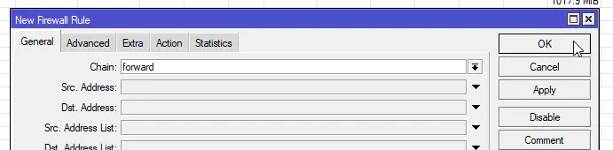
-
Open the “Firewall” window by clicking the “IP” menu and then selecting “Firewall”

-
To add a new rule, click the “+” button. A new window will open. Click “OK” to save your rule once you have finished editing it.
Firewall Rule Chains Explained
In MikroTik routers, there are three different firewall “chains” that define how the Firewall processes the rules.
- Input: Input rules apply to traffic that is entering the router (and commonly what traffic can make connections with the router directly for services like DNS and WinBox).
- Forward: Forward rules control what traffic is routed by the router. These rules usually are configured to restrict packet flow between subnets or between the LAN and WAN.
- Output: Output rules are applied to traffic that is leaving the router and being forwarded on to another device / router (such as to the internet). These rules are not commonly used.
-
Firewall rules are evaluated in priority order. On the far left, the “#” column shows the order that the rules are evaulated. We need to update the priority of our new rule, which we can do by dragging it to where we want it to go.

The new rule will take effect immediately.
Example Firewall Rules
Removing or modifying the default rules could open up your network to attacks.
Please only do this if you are absolutely sure you know what you are doing!
All rules listed on this page are for example purposes only. They are not guaranteed to protect your network from attackers or prevent you from being hacked. Use at your own risk.
Here are some example firewall rules. You may have to play with the priority to get the rules to work correctly (especially if you add combinations of the rules listed below).
- Values not listed are intended to be left as their default values or not set.
- Any value with “!” in front of it means to select the “!” or “not” button to the left of the textbox.
Block traffic between VLANs but allow traffic to the internet
Create a new rule with the following:
- General - Chain:
forward - General - In. Interface List:
LAN - General - Out. Interface List: !
WAN - General - Connection State: Select “established”, “related”, “new”, “untracked”
- Action - Action:
drop
Block traffic from Server VLAN but allow traffic from User VLAN to Server VLAN
Create a new rule with the following:
- General - Chain:
forward - General - In. Interface:
Server VLAN - General - Out. Interface List:
LAN - General - Connection State: Select “new”
- Action - Action:
drop
Block traffic to the internet, except on ports 80 and 443
This firewall rule requires 2 rules. Make sure that they are in the order listed below:
- General - Chain:
forward - General - Protocol:
6 (tcp) - General - Dst. Port:
80,443 - General - In. Interface List:
LAN - General - Out. Interface List:
WAN - Action - Action:
accept
- General - Chain:
forward - General - In. Interface List:
LAN - General - Out. Interface List:
WAN - General - Connection State: Select “new”
- Action - Action:
drop
Block traffic to WinBox except on the management VLAN
Create a new rule with the following:
- General - Chain:
input - General - Protocol:
6 (tcp) - General - Dst. Port:
8291 - General - In. Interface: !
bridge - Action - Action:
drop